Otrona Attache

General description

The Otrona Attache, introduced in 1982, was a vintage portable computer that utilized a special 8086 module to run DOS version 2.11 in addition to CP/M 2.2.
Here’s the revised description with this information included:


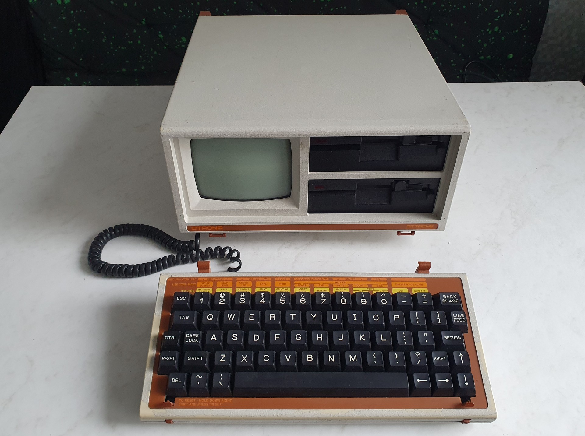
    • Otrona Systems, Inc. produced the Otrona Attache, a compact portable computer designed for business professionals and executives who needed computing power on the go.


    • The Otrona Attache debuted in 1982, coinciding with the early years of the personal computer revolution.


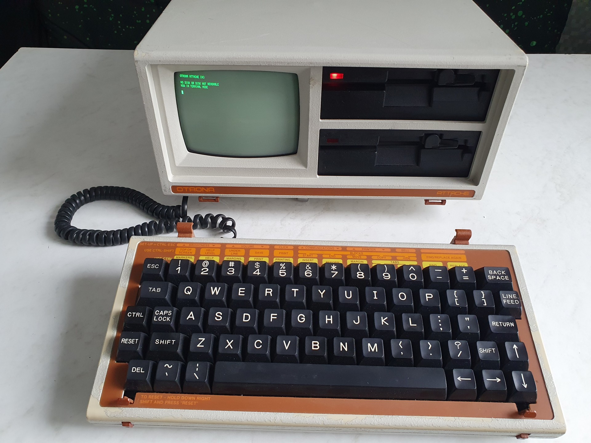
    • Featuring a built-in folding keyboard and a small built-in display, the Attache was convenient for mobile computing tasks.


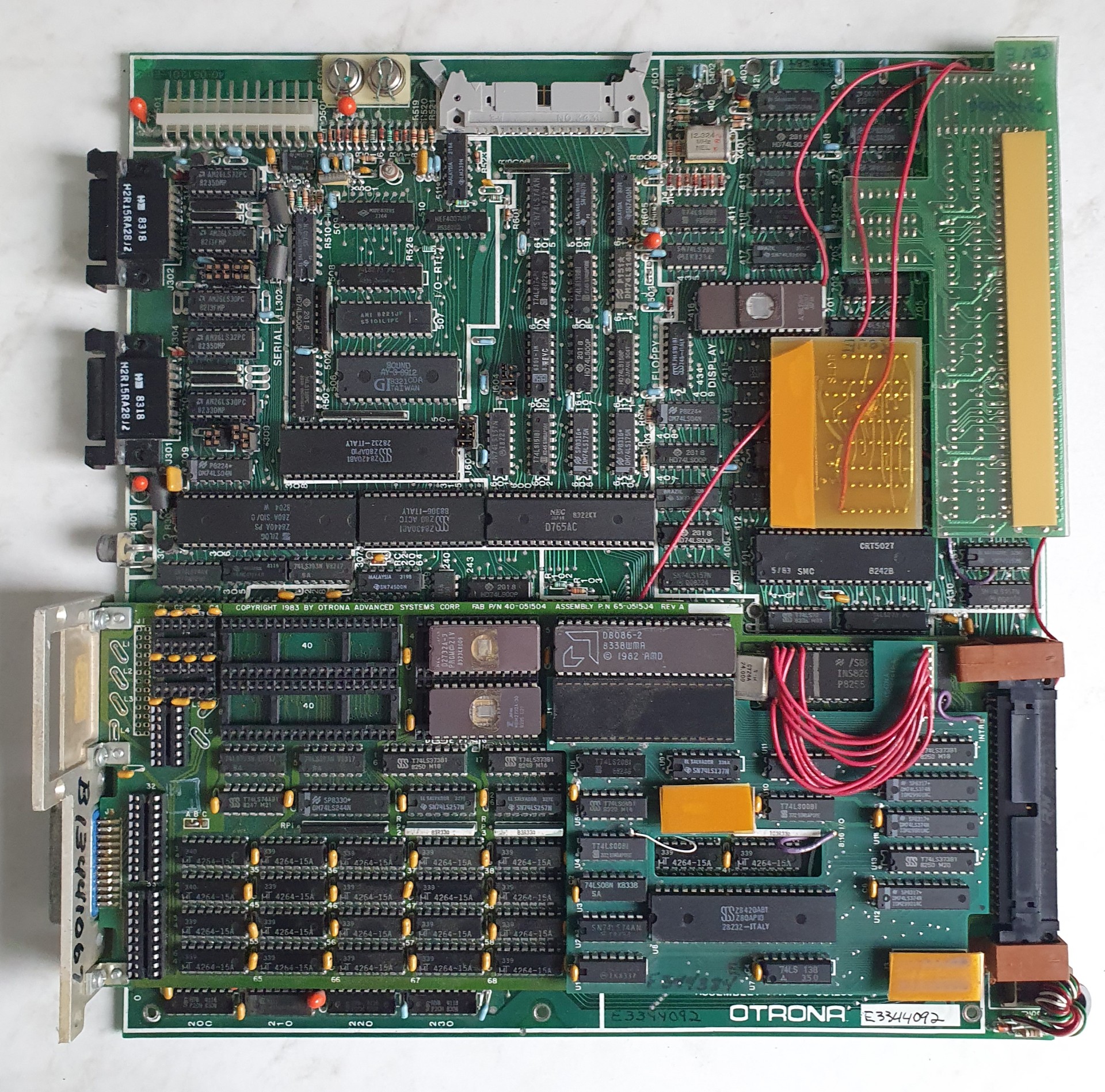
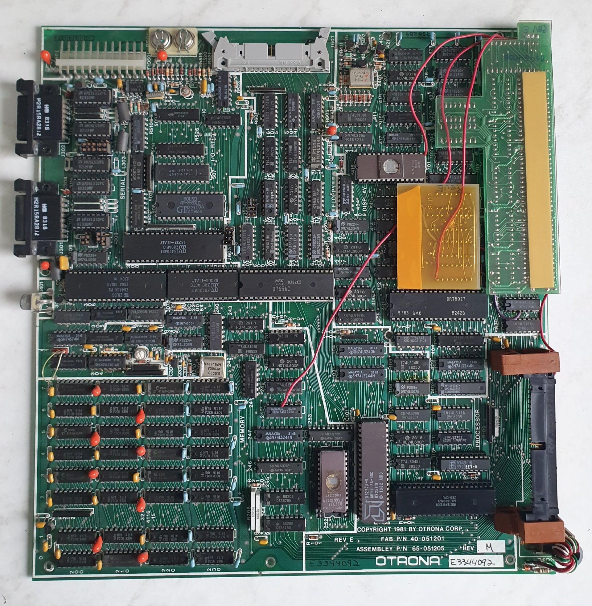
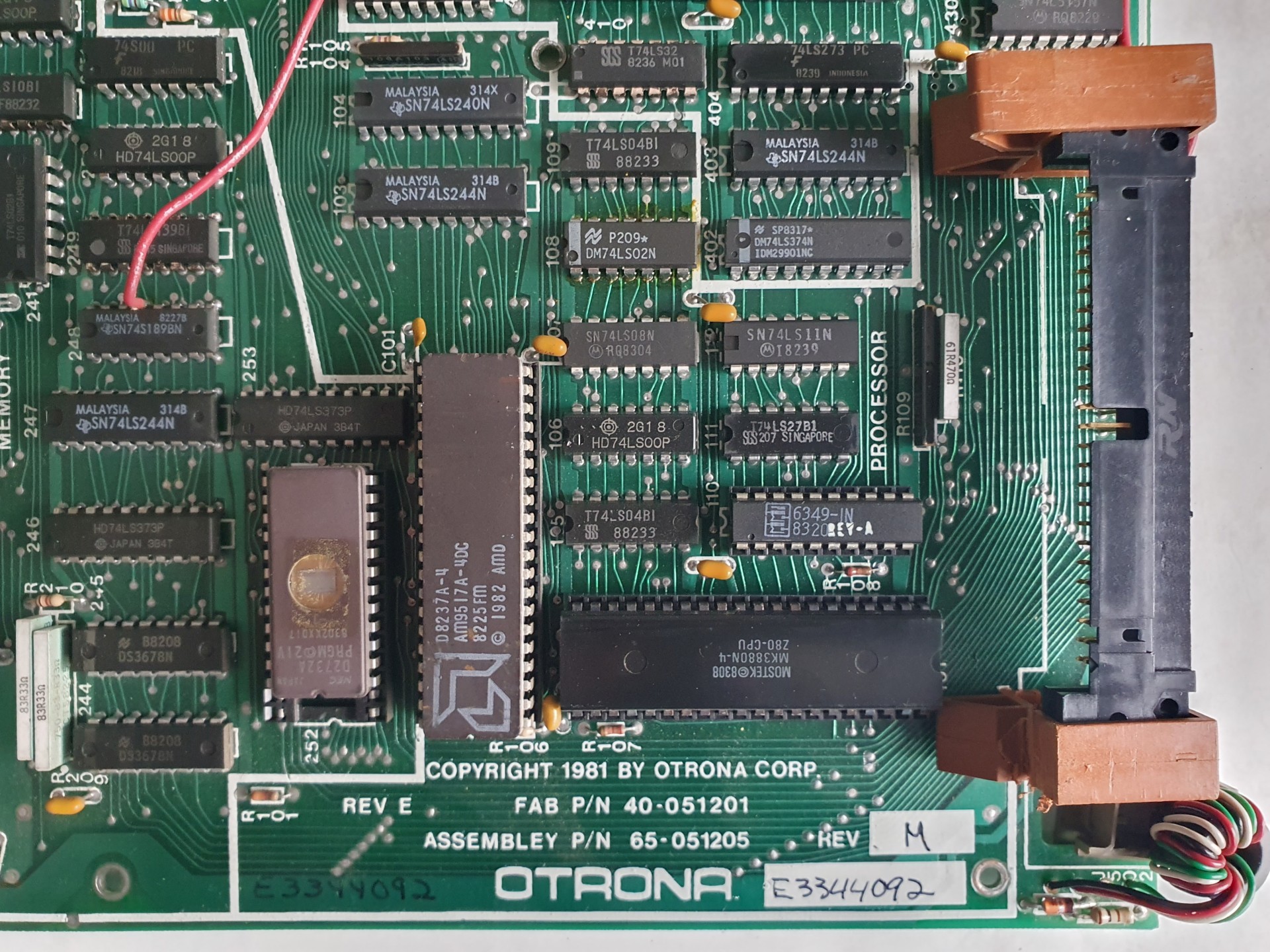
    • Powered by a Zilog Z80 microprocessor, the computer typically had 64 KB or 128 KB of RAM. Additionally, it featured a special 8086 module that enabled it to run DOS version 2.11 alongside CP/M 2.2.


    • The Otrona Attache offered dual operating system compatibility, allowing users to choose between CP/M 2.2, a widely used system in the early 1980s, and DOS version 2.11. DOS 2.11 provided users with a command-line interface and expanded software compatibility.


    • The Attache utilized 5.25-inch floppy disks for storage, allowing users to save and retrieve their data.
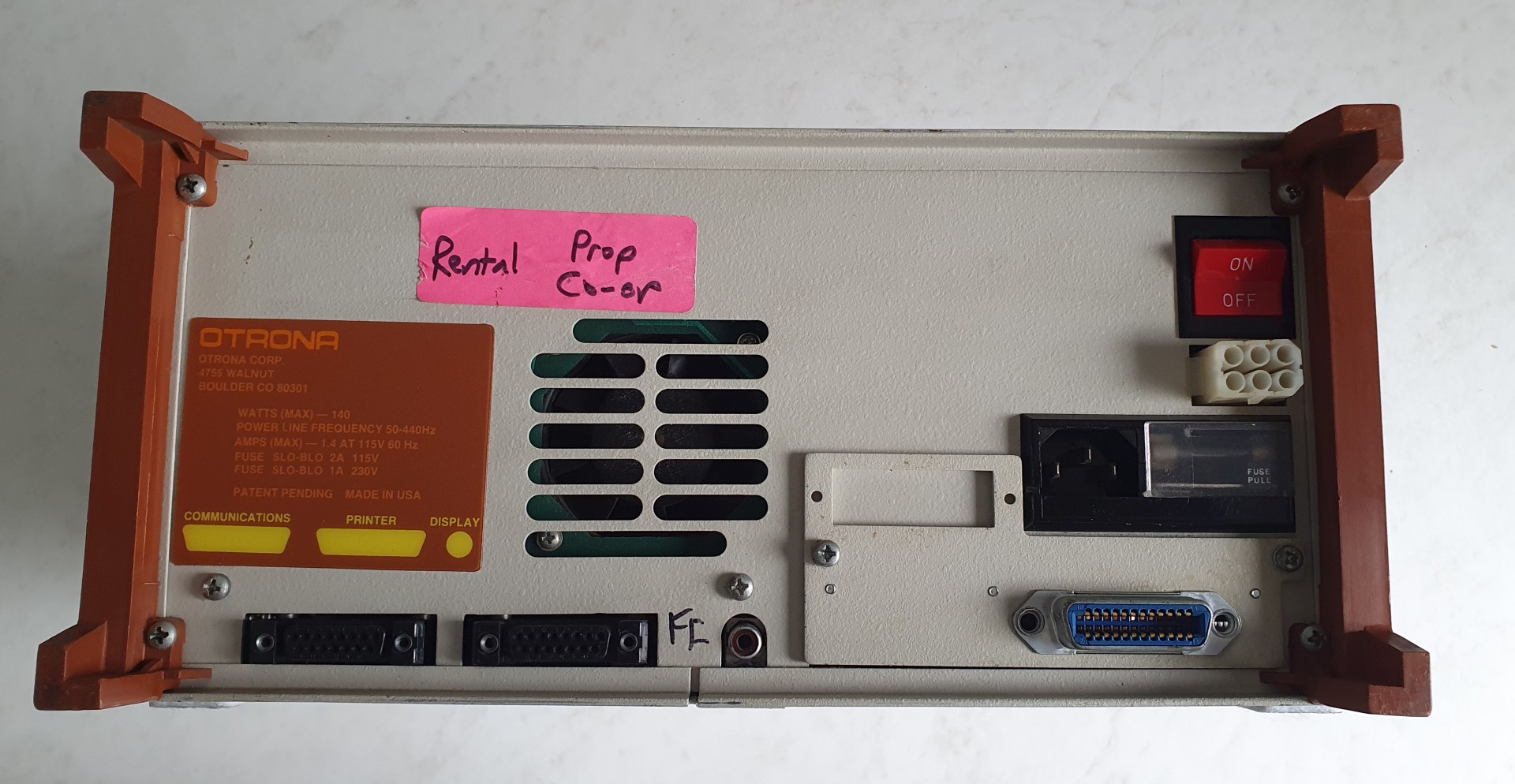
    • It featured ports for connecting external peripherals such as printers and modems, expanding its functionality.


    • Primarily utilized for word processing, spreadsheet calculations, and other productivity tasks on the go, the Attache catered to professionals needing computing capabilities outside of traditional office environments.


  • Despite not achieving the same level of recognition as some contemporaneous portable computers, the Otrona Attache contributed to the advancement of portable computing technology and laid the groundwork for modern laptops and notebook computers.

In summary, the Otrona Attache stands as a significant example of early portable computing technology, leveraging a special 8086 module to offer dual operating system compatibility and deliver mobile computing capabilities to business users in the early 1980s

Internal structure

Attache’s logic sections on the processor board are the processor, memory, serial, display, Input/Output and Real-Time Clock (I/O – RTC), floppy, and graphics. The four remaining Attache modules contain separate logic boards. These are the power supply, the keyboard, the display module, and the diskette drives.

The Central Processing Unit (CPU) is the central intelligence of the Attache system. The CPU’s address and data lines form a system bus. This system bus provides the means for the logic sections, hardware modules, and peripheral devices to interface.

The Direct Memory Access controller (DMA) operates in parallel with the CPU. The DMA handles data transfers between memory locations and Input/Output (I/O) devices by taking control of the system bus. Either the DMA or the CPU controls the system bus at any given time.

An I/O selector identifies the I/O device which interfaces with the processor.

An Erasable Programmable Read-Only Memory (EPROM) chip loads the bootstrap routine into Random Access Memory (RAM). The bootstrap routine is the program which starts up the system. The EPROM is then disabled, which allovls RAM to be accessed. The EPROM contains the Terminal Emulation routine, the Monitor Mode, system diagnostics, and pointers to the diskette location to load the Control Program for Microcomputers (CP/M) operating system.

An Expansion Connector allows a variety of external devices to interface with the Attache system via the system bus.

The memory block represents 64K bytes of Random Access Memory (RAM). Attache uses Dynamic RAM, which requires refreshing. These refreshes are timed by Row Address S~robe/Column Address Strobe (RAS/CAS). Virtual mapping allows software to relocate any 8K byte memory region to any other memory region.

Attache’s 23 KHz switching power supply powers all the system modules. The Power Okay signal ensures power is properly stabilized before the processor is initialized.

Two ports allow periphe~al devices to communicate with the system via the Ser ial Input/Output controller (SIO).

A Counter Timer Controller (CTC) generates two clock signals which produce baud rates for the ports. Additionally, two CTC channels are used in the 60 Hz Interrupt Routine and Floppy Interrupt Routine process.

The display logic contains a CRT controller which synchronizes the video signals and addresses data transfers between the· display and the processor. The display constantly reads information from the display memory as it refreshes the screen. The CPU updates the display memory as display data changes.
Display memory is 4K bytes of alphanumeric RAM and 10K bytes of graphic RAM. The alphanumeric data is combined with the attributes and a character generator EPROM outputs the data bits which comprise ·the ASCII characters. The data is then shifted to the display module. Data is read back from the display memory to the processor through the same logic paths.

The floppy controller writes or reads data from the diskette. Data and clock information are written on the same diskette track. Clock pulses are separated from the data by a data separator as data is read back to the processor. Write precompensation ensures that data is written at the correct diskette location.

A Parallel Input/Output controller (PIO) allows additional de~ices to interface with the system bus without increasing the capacitive load on the bus.

The devices which connect to the PIO are:

  • the Real-Time Clock (RTC), which performs time of day functions,
  • Complementary Metal-Oxide Semiconductor Random Access Memory (CMOS RAM), which stores system parameters
  • a sound synthesizer, which provides keyboard feedback and is software programmable for other sounds,
  • a control latch that controls CRT brightness, generates EPROM enable, controls the floppy motor, and generates graphic enable, and
  • the keyboard, which provides system reset control, data input, and control input.

IBM-PC Compatibility

When operated as a 16-bit computer with MS-DOS, Attache 8:16 is software-compatible with the IBM 5150 Personal Computer (PC).
This means that most software written for the IBM PC can be run on the Attache 8:16.

To run the Otrona Attache in Microsoft DOS mode, the computer must be equipped with the 8086 module.

Attache 8:16 provides IBM-PC compatibility in the following ways:

Operating System – Attache 8:16’s enhanced version of Microsoft’s MS-DOS 2.0 is fully compatible with the IBM PC-DOS 2.0.
The differences between IBM’s PC-DOS and the Microsoft „generic” MS-DOS result from the IBM PC’s physical and logical architecture.
Many operations that would normally be handled by the operating system (such as logical input/output instructions) are reduced to microcode instructions in the PC’s ROM.
Since IBM’s ROM is proprietary, Attache’S MS-DOS handles these functions in the portion of the operating system known as the BIOS (Basic Input Output System). This section of MS-DOS (IO.SYS) has been customized for Attache 8:16 to emUlate the PC’s microcode.
Attache 8:l6’s BIOS for MS-DOS is completely PC-compatible.
Any program written for the PC that performs all input/output operations through IO.SYS will run without modification. For programs that are written to the IBM ROM rather than the BIOS, Attache 8:l6’s BIOS emUlates PC I/O port routines. This allows Attache 8:16 to run most applications software that is written for the IBM-PC.
Diskettes – Attache 8:16 reads and writes disks in the same format as the PC, so data disks can be freely exchanged between the two machines.
You cannot actually boot a PC-DOS operating system diskette on Attache 8:16, but you can insert the disk and run the programs after you have loaded MS-DOS from the Attache DOS diskette.

Otrona-Attache_DOS_mode_screen

Attache 8: 16's Dual Processors

The Attache 8:16 is actually two computers in one. As a l6-bit computer, the 8:16 uses an 8086 processor and 256K bytes of RAM with the MS/DOS 2.0 operating system.

As an 8-bit computer, the 8:16 uses a Z-80A processor and 64K bytes of RAM with the CP/M operating system.
CP/M and MS-DOS cannot be run simultaneously.
Either system is selected automatically by simply loading the appropriate software. If a disk containing MS-DOS is loaded, the computer is in l6-bit mode running MS-DOS.
If a disk containing CP/M is loaded, the computer is in 8-bit mode running CP/M.
Attache 8:16 automatically configures the keyboard, disk format, graphics format, and input/output structure for the selected mode of operation each time a system is loaded.


Below is an example of booting the CP/M system on the Otrona Attache computer.

Otrona-Attache_CPM_mode_screen